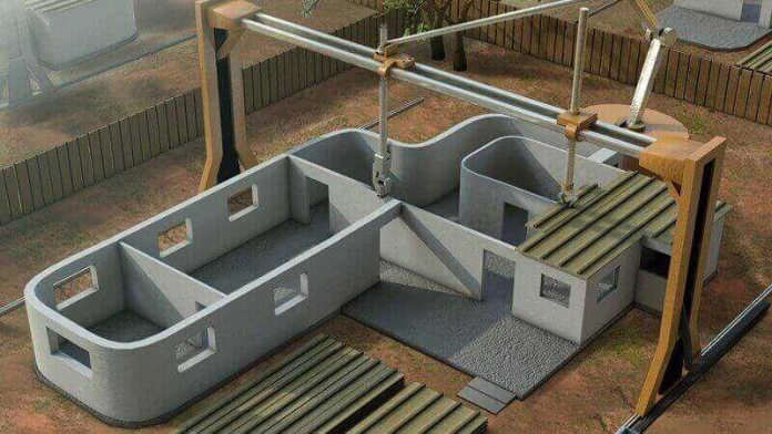
Construction drawings are graphical representations of the structure that has to be constructed, the layout in which it will be laid, detailed drawings of different aspects of the structure and their dimensions. Drawings lead the different teams working on distinct tasks to complete them as per requirement.
Some of the major construction drawings type are as follows :
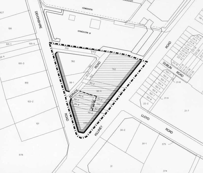
Block Plan - It is a drawing of the structure along with adjacent components depicted on a map drawn to scale. This plan gives the idea of roads, boundaries of nearby buildings, etc. that are needed to analyse the construction site. It helps the constructing firm to know the objectives related to the project. It is generally built to scale from 1:2500 - 1:500.
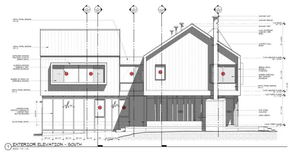
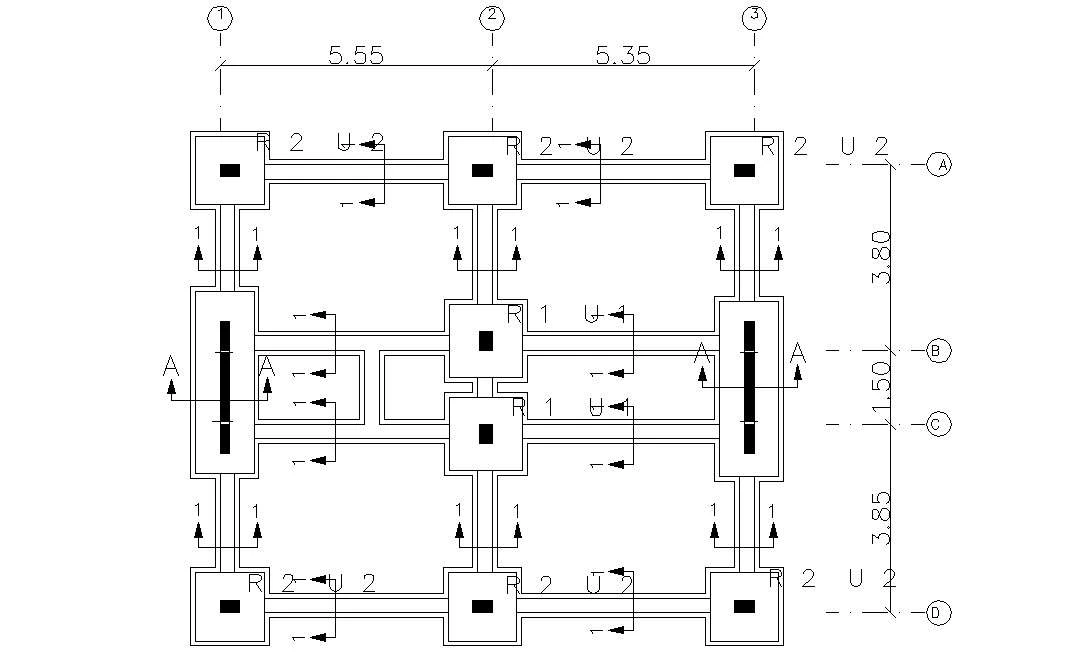
Architectural Drawing - These drawings assist in knowing the layout of the structure and the dimensions associated with it. These drawings are referred to before the construction begins. More accurately, these drawings act as blueprints of the structure that has to be built. Architectural drawings commonly used are Foundation Plan, Floor Plan, Sectional Drawing, Elevation Drawing, etc.
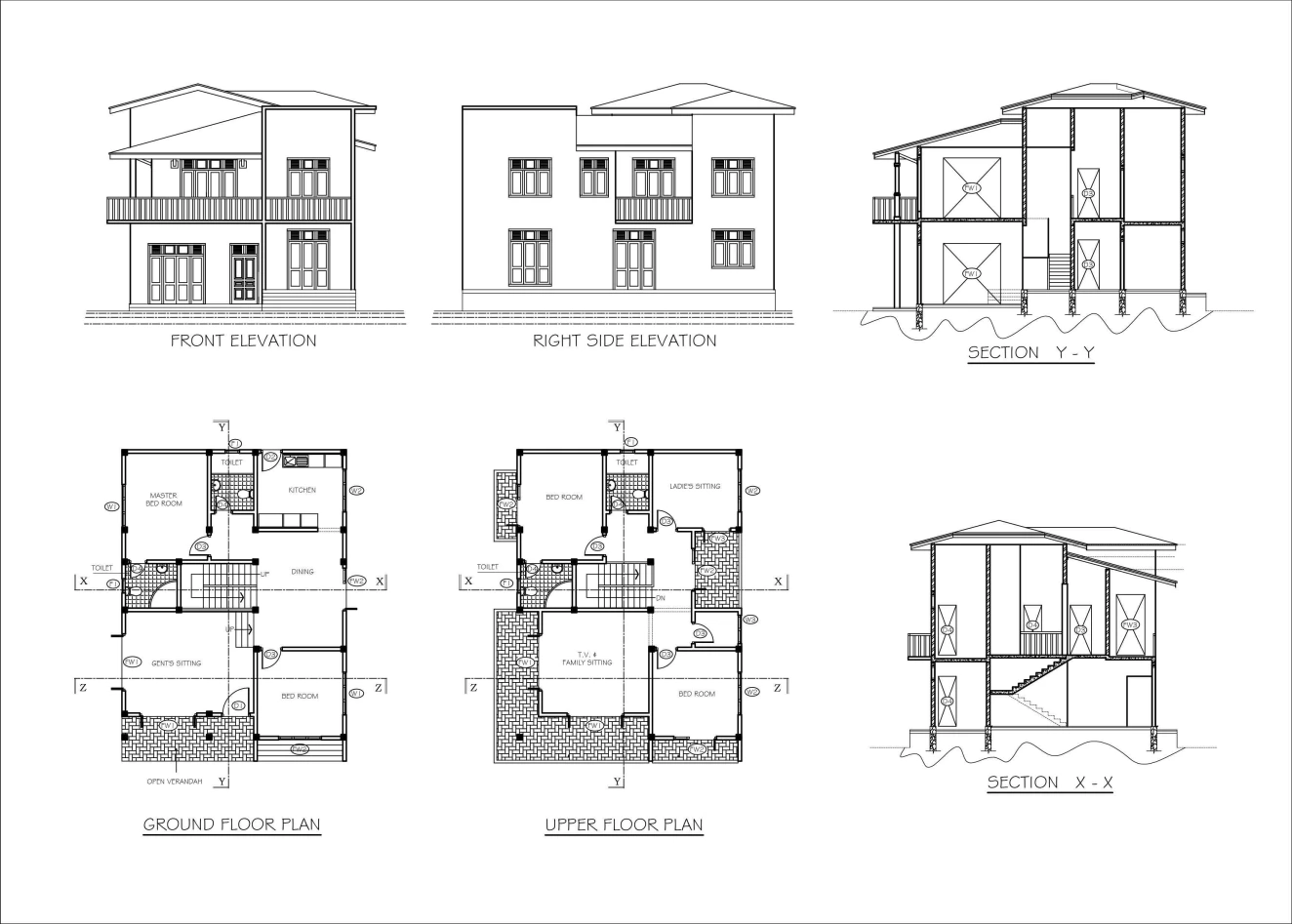
Production Drawing - These drawings fulfil the functional requirements related to different tasks to be performed by the individual or teams involved. For all structural parts that have to be built each of it needs a pre planned set of materials, tools, equipment, workforce and regulatory information. All these details can be found in Production drawings. This may also contain the process that needs to be followed in acquiring these components**.**
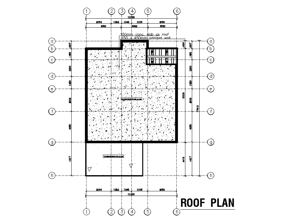
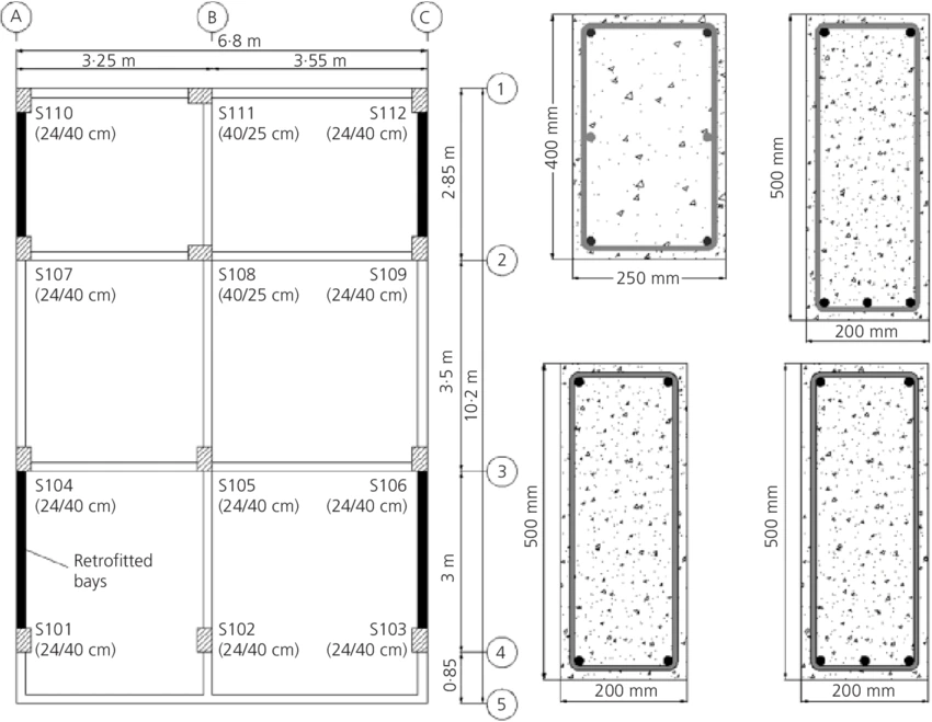
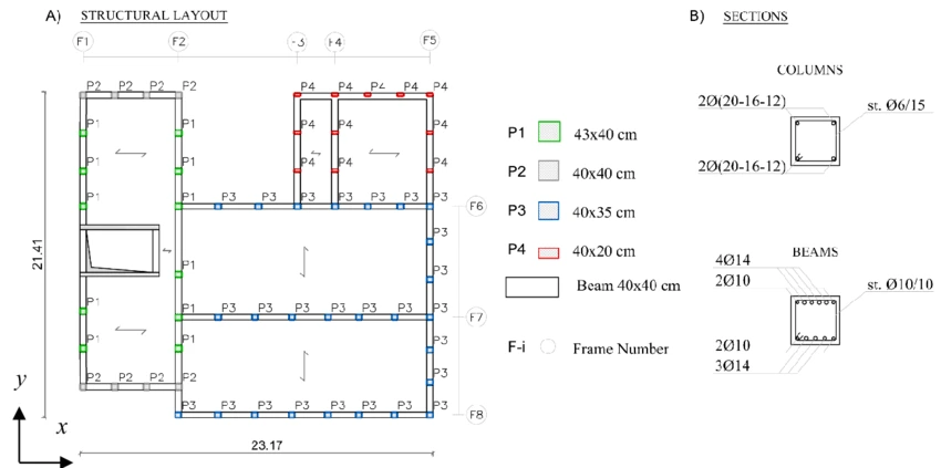
Structural Drawings - These drawings are commonly known as Civil Engineering drawings. These drawings depict the bits and pieces of a structural skeleton which are used as guide by the site engineers and workers. Common types of structural drawings used are General Notes, Excavation Drawing, Column Layouts, Beam Layouts, Roof Slab Layouts, etc.
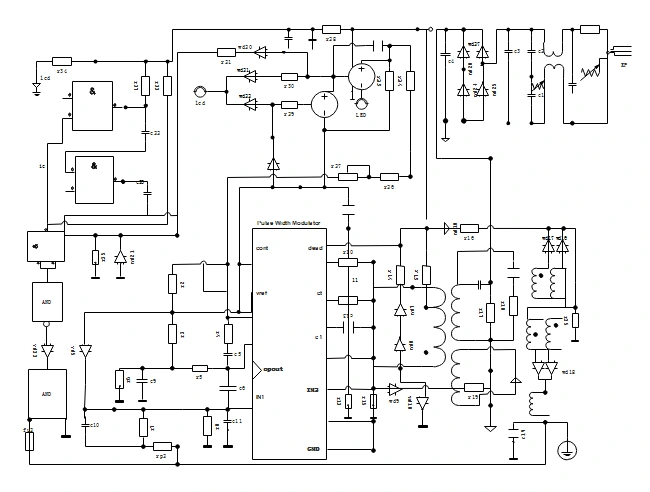
Electrical Drawings - The purpose of making these drawings is to depict the layout of the power outlets, light and fan fixtures, that are to be installed in the structure. The wiring pattern and electrical loading borne by the different power outlets are also laid out in these drawings. Common details that are usually included in electrical drawings are earthing layout, light and fan fixture layouts, cable tray layout, generators, protection systems, etc.
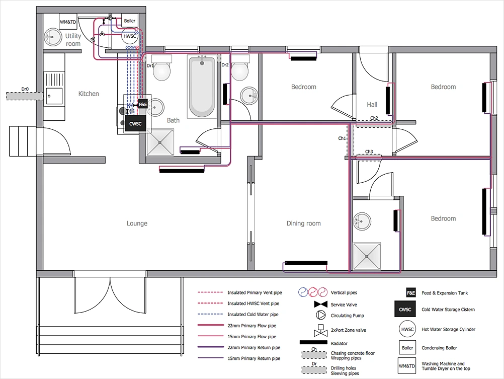
Plumbing Drawings - In a similar way like electrical drawings, plumbing drawings also need to be included in construction drawings for residential or commercial buildings. These maps comprise the plumbing patterns that need to be set up like taps, basins, water closets, pipelines, groundwater motor pipes, etc. These are used once the structural construction aspect of the project is accomplished. Plumbing drawings include different pipes layout and their materials, outlet points and their positions.
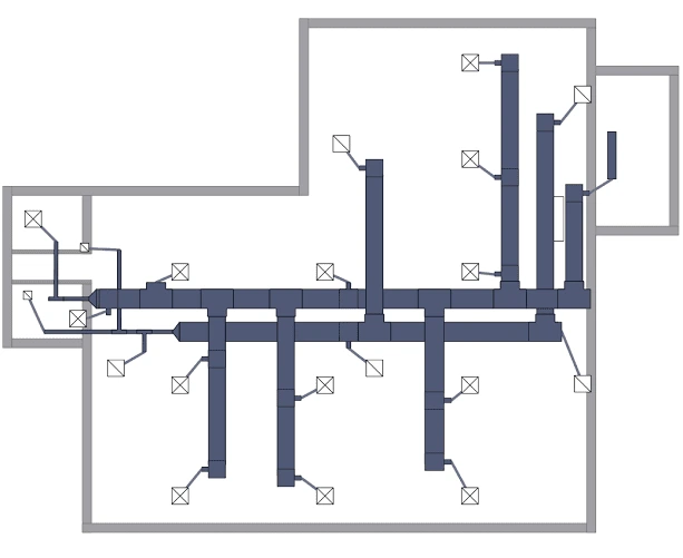
HVAC Drawings - These are mechanical drawings of a structure that depict the framework for heating and ventilations systems. These drawings have details about the central heating patterns, ventilation lines and outlets as per structural and site requirements.
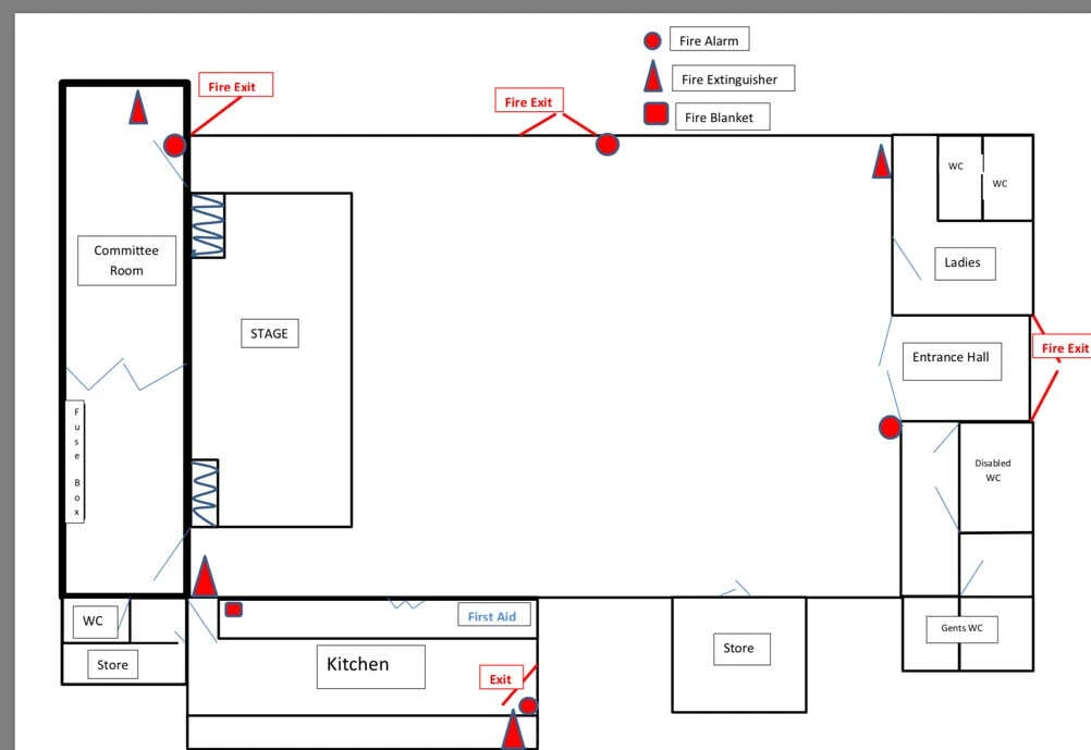
Fire Fighting Drawings - As the name suggests these drawings depict the provisions that need to be provided for safeguarding the structure and inmates in emergency situations. These drawings have the locations where fire hoses, escape routes, water outlets and other safety amenities are to be installed.
Environmental Plans - These plans typically present the environmental friendly steps and methods that need to be adopted in the construction process. These are prepared to discourage practices that affect the environment in a more adverse manner. The main purpose of these drawings is to minimize environmental damage and future negative impacts of the construction project.
Finishing Drawings - These drawings include the minute and more detailed plans of the structure after the overall framework has been constructed. This is generally prepared for the aesthetic and functional value of the structure. These drawings consist of tile and floor patterns, ceiling designs, plaster and paint patterns, woodwork, motif and other designs.
